Flowserve Electric Valves Wiring Diagram
1 typical wiring diagram, three-phase with control package, mod-20 Control station and control valve in the process piping Understanding valve positioners
Wiring | Flowserve NRS 1-7 User Manual | Page 15 / 20 | Original mode
Flowserve limitorque l120-85 electric actuator iom Flowserve 1039s120ar6 pneumatic actuator & valve Priority flow regulator valves • related fluid power
Flowserve mw forced
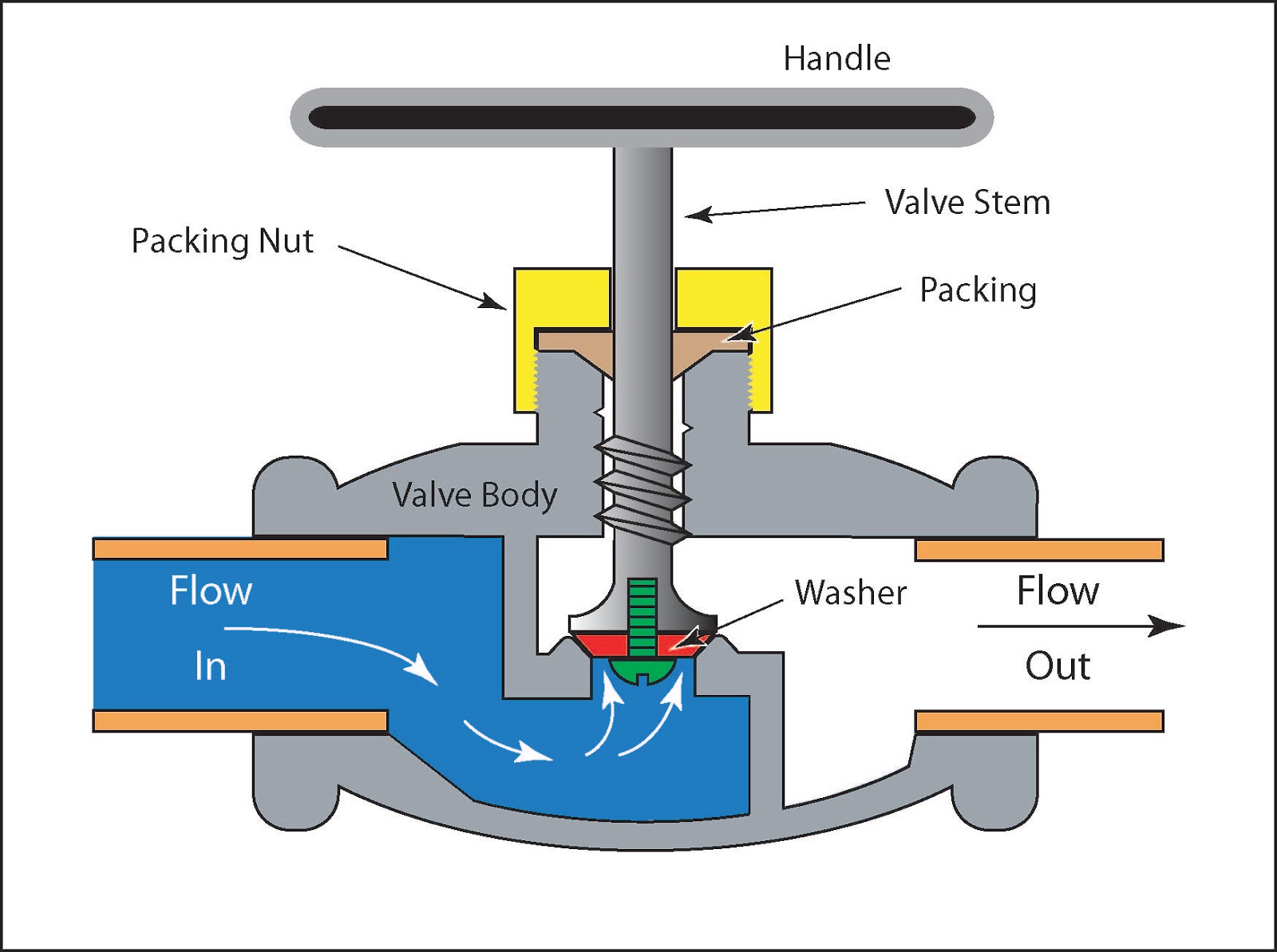
Valve working principle basic globe plug labelsElectric valve actuator wiring diagram Flowserve nrsWiring actuator typical diagram l120 flowserve phase package manual mod control ii three user model manualsdir.
Valve positioner control loop flow positioners gif process ives equipment diagram engineering function typical usingValve actuator diagram actuators rotork reversible s4 Standard wiring diagrams, 49 limitorque, figure 9.1 – wiring diagramLimitorque actuator flowserve l120 iom electric slideshare.

Flowserve limitorque l120-85 electric actuator iom
Piping station processFlowserve valve actuator pneumatic Flow priority regulator valves circuit valve control hydraulic power tankElectronic expansion valves: the basics.
Limitorque wiring l120 actuator flowserve iomL120 limitorque flowserve diagrams Expansion electronic valves valve eev motor cutaway assembly basics drive step control figure achrnews.


